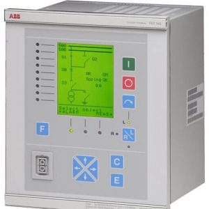
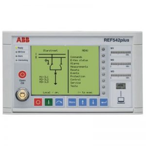
PM866AK02 任何绘制为常开的虚拟触点都将打开
¥8,870.00

Description
The reset button is connected to discrete input channel 0 when the pressure switch is connected to discrete input channel 4. The PM866AK02 warning light is connected to the discrete output channel 5. The LED indicators next to each I/O terminal and at the top of each module visually indicate the electrical status of the I/O points, while the green highlighted display shows the status of the “contacts” and “coils” in the virtual power PLC program, displayed on the screen of the personal computer connected to the PLC through programming cables.
When no one presses the reset button, the PM866AK02 switch will be in a normal state, which is open for the “normally open” switch. The same goes for pressure switches: when the process pressure is high enough to exceed the trigger point of 270 PSI, the pressure switch will also be in a normal state. For a “normally open” switch, this state is open. Because both switches are currently non-conductive, and the discrete input is also non-conductive, channel 0 and channel 4 will be activated. This means that the “virtual” contacts in the PLC program will also be in a normal state. Therefore, any virtual contact drawn as normally open will open (without transmitting virtual power), while any virtual contact drawn as normally closed (marked with a diagonal line on the contact symbol) will close. That’s why the two normally open virtual contacts In. 4 and Out. 5 are not highlighted, but the normally closed virtual contact In. 0. Please remember that the colored highlight represents the ability to pass through the virtual logic power supply, rather than an indicator of the actual current flowing through the switch.


Reviews
There are no reviews yet.